
Toolholders
Product catalogue Pafana 07/2020
Toolholders page no. 11-133 – file pdf. To download (21 mb.)

TOOLHOLDERS OF PAFANA.
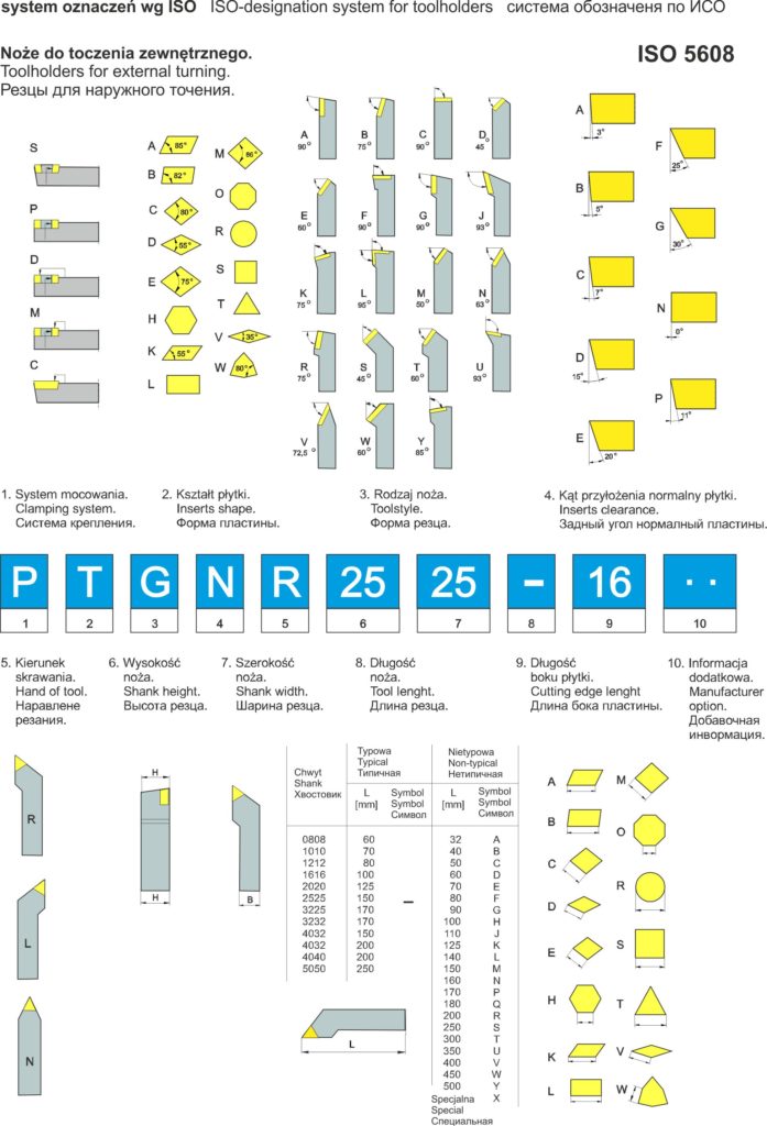
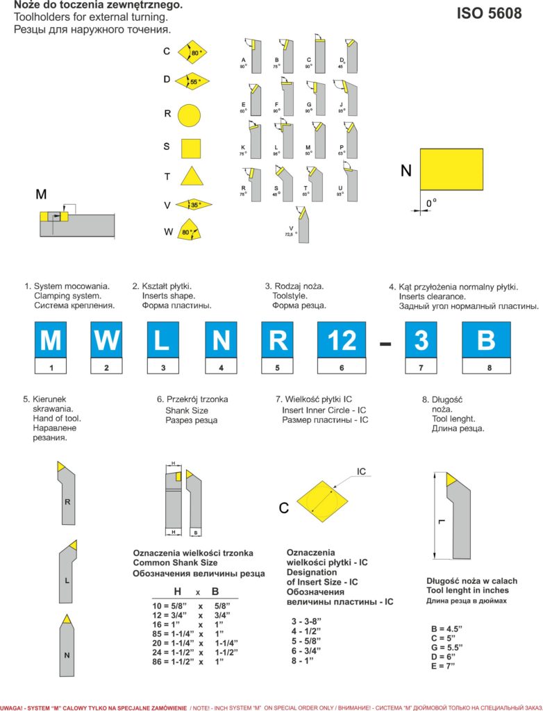
iso-designation system for Pafana toolholders for external turning
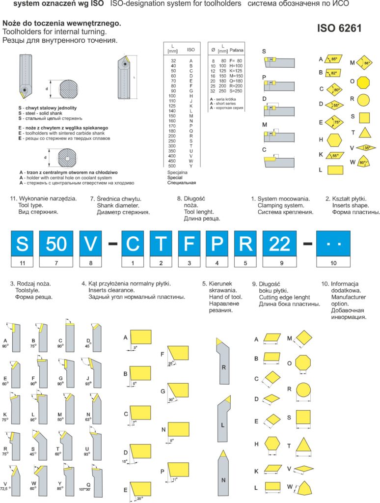
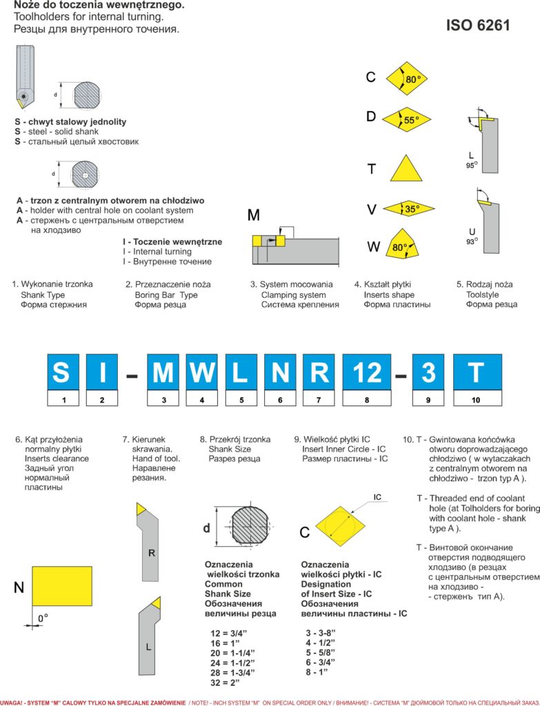
iso-designation system for Pafana toolholders for internal turning
CLAMPING SYSTEMS FOR INSERTS.
SYSTEM S
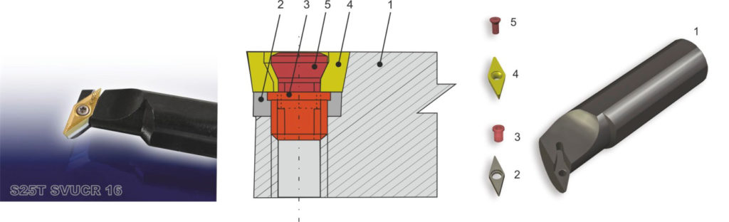
1 – holder.
2 – shim.
3 – shim screw.
4 – cutting insert.
5 – locking screw.
Clamping system for inserts – „S”.
„S” SYSTEM „zero” geometry of the seat -most toolholders for external turning, positive or negative (internal turning) geometry of toolholders. Indexable, single-sided inserts locked on the conical and arched hole with a screw with conical head. „S” system is the most popular system for clamping the indexable inserts. It is characterised by simplicity, high reliability and a very good repeatability of cutting edge position as well as the possibility of clamping the inserts of very small dimensions. The principal area of using the toolholders clamped in „S” system is finishing of external surfaces and hole surfaces (especially holes of small diameters), but they are also used for roughing.
assortment index / page No. in catalogue
STDCR/L 23
STTCR/L 23
STCCN 23
STGCR/L 23
STFCR/L 23
SSDCN 23
SSSCR/L 23
SSRCR/L 24
SSKCR/L 24
SCGCR/L 24
SCFCR/L 24
SCLCR/L 24
SCLCR/L…P 24
SDNCN 25
SDNCN 25
SDNCN….-11P 25
SDJCR/L 25
SDHCR/L 25
SVJBR/L 25
SVVBN 25
SVJCR/L 25
SVVCN 25
SVJBR/L…P 26
SVVBN…P 26
SWLCR/L 26
SRDCN 26
SRGCR/L 26
S…-SSKCR/L09 27
S…-STFCR/L11 27
S…-SCLCR/L06 27
S…-SCLCR/L09 27
S…-SDUCR/L07 28
S…-SDUCR/L11 28
S…-SDUCR/L11-X 28
S…-SDQCR/L11 28
S…-SVUBR/L16 28
S…-SVUCR/L11 29
S…-SVUCR/L16 29
S…-SVQBR/L16 29
S…-SVQCR/L16 29
S…-SWLCR/L06 29
A…-SCLCR/L09 30
A…-SCLCR/L06 30
A……-SCLCR/L06 30
A…-SCFCR/L06 30
A…-SCXCR/L06 31
A…-SDUCR/L07 31
A…-SDUCR/L11 31
A…-SDQCR/L07 31
A…-SDQCR/L11 31
A…-SSSCR/L09 31
A…-STFCR/L09 32
A…-STFCR/L11 32
A…-STFCR/L16 32
A…-SVUCR/L11 32
A…SVQBR/L 16 32
A…-SVUBR/L16 32
A…-SVQCR/L11 33
A…-SVQCR/L16 33
A…-SVUCR/L11 33
A…-SVUCR/L16 33
A…-SWLCR/L08 33
BORING BARS WITH SINTERED CARBIDE SHANK
E…-SCLCR/L ..R 34
E…-SDUCR/L 07-XR 34
E…-SDUCR/L ..R 34
E…-STFCR/L ..R 34
TOOL HOLDERS VDI PTA – 20 (28)
PTA- 20 34
PTA-28 34
TOOLHOLDERS FOR AUTOMATIC LATHES
SDACR/L 36
SVACR/L 36
BORING CARTRIDGES
SCSCR…CA 35
SCTCR…CA 35
SCFCR/L…CA 35
SCGCR/L…CA 35
SCLCR/L…CA 35
SSKCR/L…CA 35
STFCR/L…CA 35
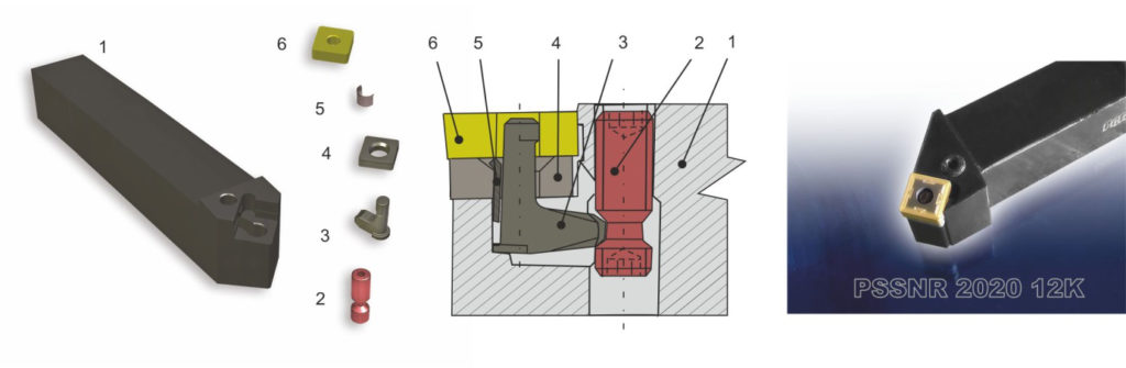
SYSTEM P
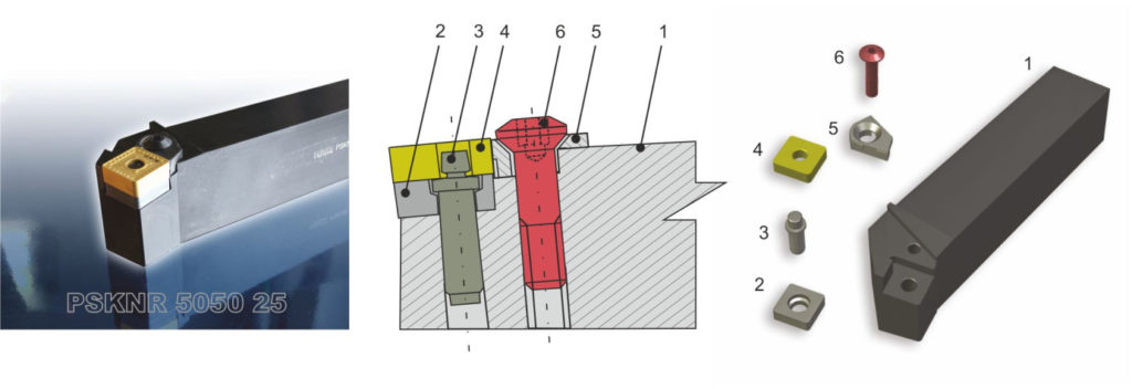
1 – holder.
2 – shim.
3 – pin.
4 – cutting insert.
5 – wedge.
6 – locking screw.
Clamping system for inserts – „P”.
„P.” SYSTEM – negative geometry of toolholders.
Negative indexable inserts (insert clearance angle 0°, triangle, square and diamond shaped, are locked on the surface of the cylindrical hole with a pin, a wedge clamp and with a locking screw.
Toolholders with inserts clamped in the „P” system are used for roughing.
„P” system is characterised by easy insert replacement, no loose clamping elements.
assortment index / page No. in catalogue
PTTNR/L 38
PTBNR/L 38
PTXNR/L 38
PTGNR/L 39
PTFNR/L 39
PTNNR/L 39
PTJNR/L 39
PVJNR/L 39
PVVNN 39
PSSNR/L 40
PSBNR/L 40
PSKNR/L 40
PCBNR/L 40
PCLNR/L 40
PDNNR/L 41
PDJNR/L 41
S…-PTFNR/L 41
S…-PCLNR 41
SYSTEM P-K
1 – holder.
2 – locking screw.
3 – lever.
4 – shim.
5 – spring sleeve.
6 – cutting insert.
Clamping system for inserts – „P-K”.
„P-K” SYSTEM – negative geometry of toolholders.
Negative indexable inserts (insert clearance angle 0°) are locked with a clamp lever on the surface of the cylindrical hole. Toolholders with inserts clamped in the „P-K” system are the best choice for effective machining, both midium and finishing, in cases when the highest rigidity and stability of clamping the insert is required, as well as enabling the chip flow (no protruding clamping elements). „P-K” system is characterised by fast and easy insert replacement, very high repeatability of cutting edge position, no loose clamping elements, convenient replacement and clamping the insert; also in the “inverted” position of the toolholder.
assortment index / page No. in catalogue
PSSNR/L…K 43
PSBNR/L…K 43
PCBNR/L…K 43
PCLNR/L…K 43
PWLNR/L…K 43
PRGNR/L…K 44
PRGCR/L…K 44
PRDCN…K 44
PTGNR/L…K 44
PTFNR/L…K 44
PTJNR/L…K 44
S…-PWLNR/L 44
S…-PCLNR/L…K 45
A…-PCLNR/L12KR 45
A…-PWLNR/L06K 45
A…-PWLNR/L08K 44-45
A…-PDUNR/L11K 45
PTFNR/L…CA 46
PTGNR/L…CA 46
PTSNR/L…CA 46
PSKNR/L…CA 46
SYSTEM D
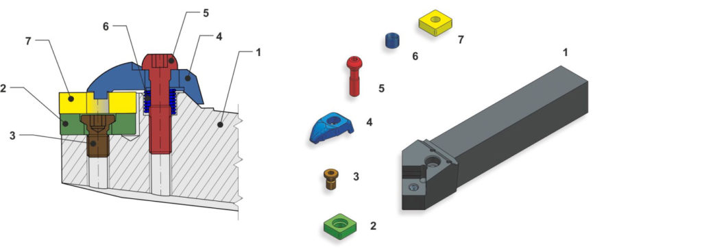
1 – holder.
2 – shim.
3 – shim locking screw.
4 – clamp.
5 – locking screw.
6 – spring.
7 – cutting insert.
Clamping system for inserts – “D “.
„D” SYSTEM – negative geometry of toolholders.
Negative indexable inserts (insert clearance angle 0°) are locked with a special clamp at the same time in two direction, i.e. on the surface of the cylindrical hole of the insert and on the rake face.
Toolholders with inserts clamped in the “D” system are the best choice for effective machining, both roughing andfinishing, requiring the highest rigidity and stability of insert position. They are used for external turning and cuttingholes. “D” system is characterised by a very good repeatability of cutting-edge position, easy and quick replacement of cutting insert. The shim and cutting insert are fixed only with one key.
assortment index / page No. in catalogue
DCLNR/L 49
A…-DCLNR/L- 12 51
DDJNR/L 49
A…-DTFNR/L- 16 51
DSSNR/L 49
A…-DWLNR/L- 08 51
DTGNR/L 50
DTJNR/L 50
DWLNR/L 50
SYSTEM M – METRIC DIMENSION.
1 – holder.
2 – shim.
3 – pin.
4 – clamp.
5 – locking screw.
6 – cutting insert.
Clamping system for inserts – “M “.
„M” SYSTEM – negative geometry of toolholders.
Negative indexable inserts (insert clearance angle 0°) are locked with a pin on the surface of the cylindrical hole and with a clamp from above on the rake face.
Toolholders with inserts clamped in the „M” system are the best choice for effective machining, both roughing and finishing, requiring the highest rigidity and stability of insert clamping.
They are used for external turning and cutting holes of large diameters (above 25 mm). „M” system is characterised by very high repeatability of cutting edge position, no loose clamping elements.
assortment index / page No. in catalogue
MCLNR/L 54
MDJNR/L 54
MDJNR/L1506 54
MDNNN 54
MDNNN1506 54
MDNNN1506 54
MSDNN 55
MSSNR/L 55
MTGNR/L 55
MTJNR/L 56
MVJNR/L 56
MWLNR/L 56
A…-MCLNR/L 12 58
A…-MDUNR/L 11 59
A…-MTFNR/L 16 59
A…-MTUNR/L 16 59
A…-MWLNR/L 06 60
A…-MWLNR/L 08 60
S…-MCLNR/L 57
S…-MDUNR/L 57
S…-MTFNR/L 57
S…-MVUNR/L 58
S…-MWLNR/L 58
MWLNR 20CA-06 60
MWLNR 20CA-08 60
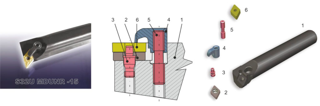
SYSTEM M – INCH DIMENSION.
iso-designation system for Pafana toolholders system M – inch dimension, external turning
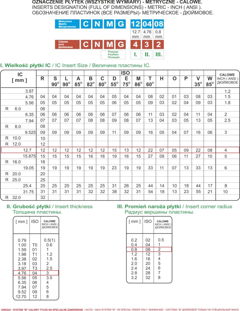
insert designation – metric- inch (ANSI)
iso-designation system for Pafana toolholders system M – inch dimension, internal turning
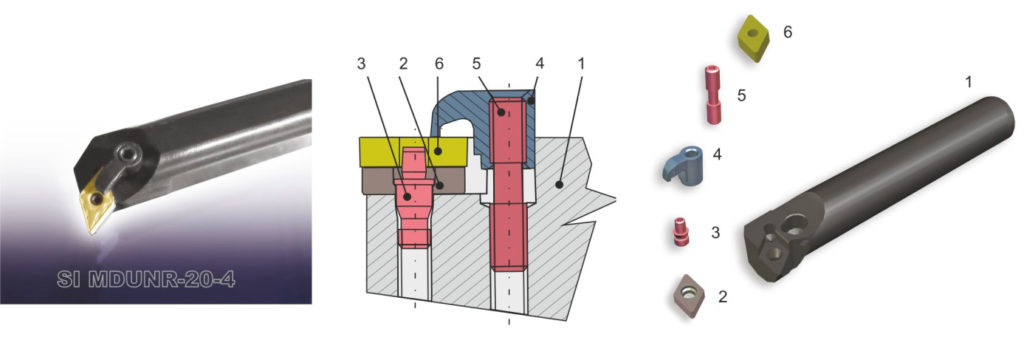
1 – holder.
2 – shim.
3 – pin.
4 – clamp.
5 – locking screw.
6 – cutting insert.
Clamping system for inserts – “M “– inch dimension.
„M” SYSTEM – negative geometry of toolholders.
Negative indexable inserts (insert clearance angle 0°) are locked with a pin on the surface of the cylindrical hole and with a clamp from above on the rake face.
Toolholders with inserts clamped in the „M” system are the best choice for effective machining, both roughing and finishing, requiring the highest rigidity and stability of insert clamping.
They are used for external turning and cutting holes of large diameters (above 25 mm). „M” system is characterised by very high repeatability of cutting edge position, no loose clamping elements.
assortment index / page No. in catalogue
MCLNR/L 66
MCMNN 66
MCRNR/L 66
MDJNR/L 67
MDPNN 67
MRGNR/L 67
MSDNN 68
MSKNR/L 68
MSRNR/L 68
MSSNR/L 69
MTENN 69
MTFNR/L 69
MTGNR/L 70
MTJNR/L 70
MVJNR/L 70
MVVNN 71
MWLNR/L 71
SI-MCLNR/L 73
AI-MCLNR/L..-T 73
SI-MDUNR/L 73
SI-MTUNR/L 73
SI-MVUNR/L 74
SI-MWLNR/L 74
AI-MWLNR/L..-T 74
SYSTEM C
1 – holder.
2 – shim.
3 – shim screw.
4 – cutting inserts.
5 – chipbreaker.
6 – locking screw.
Clamping system for inserts – “C “.
„C” SYSTEM – positive or negative geometry of toolholders.
Indexable, single-sided inserts (insert clearance angle 11°) or two-sided (insert clearance angle 0°), square and triangle shaped with flat rake face, locked on the rake face with a screw head that clamps the insert through a chip breaker made of sintered carbide, placed on the insert.
Toolholders with inserts clamped in the „C” system are used for roughing (negative geometry) and finishing (positive geometry) of external surfaces and holes (positive geometry).
„C” system is characterised by easy insert replacement and good repeatability of cutting edge position. Installed chipbreaker makes clamping difficult, but gives the possibility of chipbreaker edge position adjustment.
assortment index / page No. in catalogue
CTFNR/L 76
CTFPR/L 76
CTGNR/L 76
CTGPR/L 76
CSRNR/L 77
CSRPR/L 77
CSSNR/L 77
CSSPR/L 77
CTEPR/L 78
S…-CSKPR/L 78
S…-CTFPR/L 78
CTAPR/L 79
CTFPR/L…CA 79
CTSPR/L…CA 79
CTGPR/L…CA 80
CTTPR/L…CA 80
CSKPR/L…CA 81
CSYPR/L 81
index of chipbreakers for toolholders – Pafana system C:
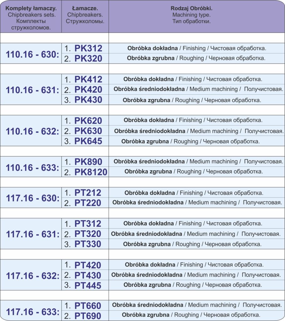
SYSTEM C – TOOLHOLDERS FOR CERAMIC INSERTS.
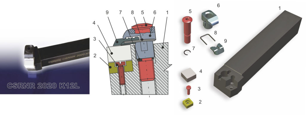
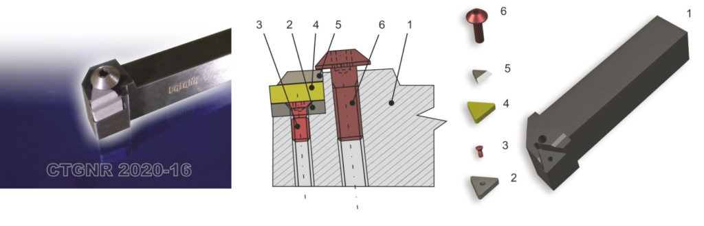
1 – holder.
2 – shim.
3 – shim screw.
4 – cutting insert.
5 – locking screw.
6 – clamp.
7 – snap ring.
8 – spring.
9 – chipbreaker.
Toolholders for ceramic inserts.
Clamping system for inserts – “C “.
Toolholder for ceramic inserts with clamping in the heavy-duty system C by means of the holding set fastening with the adjustable chipbreaker. The chipbreaker is adjustable and can be set in three different positions, in order to change the distance between chip breaker edge and the main cutting edge into: 1, 3 or 5 mm.
The replacement of the cutting edge or whole unseat is easy because when the fixing screw is loosened the complete holding set is lifted to the appropriate height.
In toolholders the indexable ceramic inserts, 7,94 mm thick, can be fixed.
assortment index / page No. in catalogue
CSKNR/L…L 84
CSSNR/L…L 84
CSRNR/L…L 84
CTFNR/L…L 84
CTJNR/L…L 84
TOOLHOLDERS FOR PARTING, UNDERCUTTING, GROOVING.
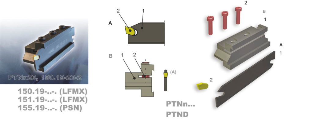
A – Blade:
1 – holder.
2 – cutting insert
B – Holder:
1 – body.
2 – locking screw.
Toolholders for parting and undercutting.
Toolholders with LFMX, PSN inserts.
Insert is clamped in toolholders due to cutting forces. The most popular tools from that group are double-edge cut off blades type 150.19-..-., 151.19-..-.-. the best toolholders for parting objects of large diameter and making deep radial grooves.
For clamping cut off blades, PTND or PTNn holders should be used. The insert should be fixed in the seat with a plastic hammer.
assortment index / page No. in catalogue
150.19 86
151.19 86
155.19 87
PTNn 88
PTND 89
152.19-32 89
TOOLHOLDERS FOR GROOVING.
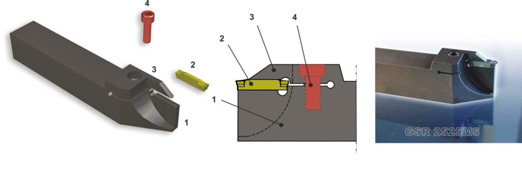
1 – holder.
2 – cutting insert.
3 – clamp.
4 – locking screw.
Toolholders for grooving
Toolholders with PTN inserts.
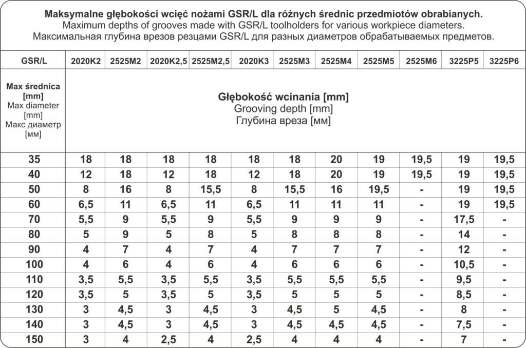
Insert clamped in the cartridge with a clamp and a screw. These are toolholders, which due to the rigid clamping of the insert transferring lateral forces, are used not only to make undercuts, grooves and for parting, but also for lengthways and contour turning. There toolholders, combined with double-edge PTN… inserts, are the most economic solution in case of parting, undercutting and grooving of groves of different width and depth: up to 18-20 mm external grooves, and up to 6-9 mm internal grooves. Inserts with straight cutting edge (rectangular) or inserts with round cutting edge (radius) can be used. Toolholders for external undercutting are available in two versions: regular GPR/L and reinforced GSR/L. Regular toolholders can be used for undercutting regarding the whole insert active depth (G). Reinforced toolholders have higher rigidity at the cost of limiting the workpiece diameter (table No.1 page 91).
Reinforced toolholders with largest possible handle cross-section and maximum insert width should always be selected in the first place.
During grooving and contour turning, the radial feed should be directed towards the workpiece axis, in order to increase the insert’s durability and limit the risk of pulling the insert out.
assortment index / page No. in catalogue
GAR/L…. 92
GSR/L…. 93
GPR/L…. PT 94
GPR/L…. PSN 94
GFR/L.. 95
S..-GSR/L….. 96
maximum depths of grooves made with GSR/L toolholders for various workpiece diameters
TOOLHOLDERS FOR THREADING.
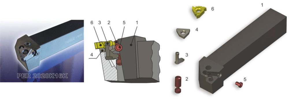
1 – holder.
2 – screw.
3 – lever.
4 – shim.
5 – shim screw.
6 – cutting insert.
Toolholders for threading.
Clamping system for inserts – „P-K”. „P-K” SYSTEM – negative geometry of toolholders.
Inserts with holes designed for external threading with thread pitch up to 3 mm (of various producers) can be installed on the PER/L… 16K toolholders. Thanks to their appropriate seat shape and lever fixing system the triangular cutting inserts of the 16 mm side length (IC=9,525 mm) are positioned and fixed properly independently of their thickness and the hole diameter. The cutting tool is equipped with a shim that provides: – protection (in case of insert’s damage), – correction (of tool geometry).
assortment index / page No. in catalogue
PER/L…K 98
SER/L11 98
SER/L16 98
S…-SIR/L11 99
S……-SIR/L16 99
S…-PIR/L16 100
S…-PIR/L22 100
SMART HEAD SYSTEM.
Modular system of boring tools with connector with replaceable heads in systems: S, M, P-K.
assortment index / page No. in catalogue
K25-SVUCL/R16 101
K32-SVUCL/R16
K40-SVUCL/R16
K25-SDQL/R11
K25-SCLCL/R09
K25-MWLNL/R08
K32-MWLNL/R08
K40-MWLNL/R08
K40-MCLNL/R19
K32-PCLNL/R12K
K25-PTFNL/R16K
chwyt:
Ø 25 A25-K25 270 102
Ø 32 A32-K32 305 102
PAFANA SMARTCUT TOOLS.
SCR2.25D08-10XP04 104
SCL2.25D08-10XP04
SCR/L2.25D10-12XP05
SCR/L2.25D12-16XP06
SCR/L2.25D14-16XP07
SCR/L2.25D16-20XP08
SCR/L2.25D18-25XP09
SCR/L2.25D20-25XP10
SCR/L2.25D25-32XP13
SCR/L2.25D32-40XP17
Tools and toolholders sets “DIY” ( do it yourself ).
4 BBS1
S0608H SCLCR 06N 116
S0810J SCLCR 06N
S1012K SCLCR 06N
S1216M SCLCR 06N
5 TS1B
SSDCN 0808-06N 116
SCLCR 0808-06N
SDJCR 0808-07N
SDJCL 0808-07N
S08H SCLCR 06N
5 TS2
SCXCN 0808-06N 116
SCLCR 0808-06N
SDJCR 0808-07N
SDJCL 0808-07N
S08H SCLCR 06